assignment
计算机作业代写 Your organisation is allocated a block of address 10.Y.0.0/22. You are required to plan the subnets. And IP addressing based on the following ···
Task(s) 计算机作业代写
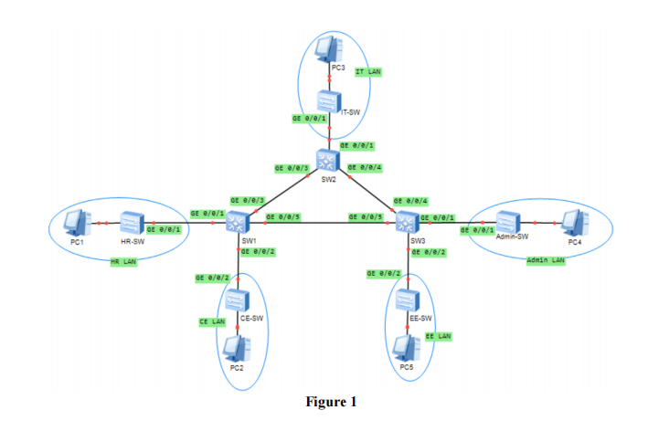
Your organisation is allocated a block of address 10.Y.0.0/22. You are required to plan the subnets. And IP addressing based on the following address allocation requirement for each subnet as shown in Figure 1.
- The IT LAN requires i8 addresses.
- The HR LAN requires j8 addresses.
- The ADMIN LAN requires k8 addresses.
- The CE LAN requires 10 addresses.
- The EE LAN requires 25 addresses.
- Each link segment between two Layer 3 switches requires 2 addresses.
Note: 计算机作业代写
- Y denotes the last two digits of your student ID.
- i denotes the third last digit of your student ID. If the digit is “0”, it is replaced with “10”.
- j denotes the second last digit of your student ID. If the digit is “0”, it is replaced with “10”.
- k denotes the last digit of your student ID. If the digit is “0”, it is replaced with “10”.
- Example 1: If your student ID is DMT19091234, the address block that you use in this
assignment is 10.34.0.0/22. The IT LAN requires 28 addresses. The HR LAN requires 38 addresses. The ADMIN LAN requires 48 addresses.
- Example 2: If your student ID is DMT1909100, the address block that you use in this assignment is 10.0.0.0/22. The IT LAN requires 18 addresses. The HR LAN requires 108 addresses. The ADMIN LAN requires 108 addresses.
Complete the following tasks.
Task 1. Subnet Planning and Layer 3 Switch Configuration 计算机作业代写
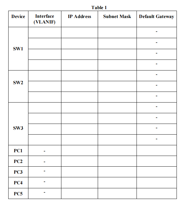
- Perform subnet planning for your organisation’s network. Show your work. 2. Assign VLAN ID and list the following address information for each subnet1:
- Network address
- Usable IP address range
- Broadcast address
- Decimal / CIDR Subnet mask
- Table 1 is used for your configuration plan. Fill in the IP address and subnet mask for each of
the PC and VLANIF’s interface.
-
Connect each device as shown in Figure 1. 计算机作业代写
- Select “S5700” in eNSP as the Layer 3 switch for SW1, SW2, and SW3. (You can use
S3700 if there is any issue of using S5700 with your eNSP).
- Use “S3700” in eNSP for the remaining switches in the diagram.
- You can select any appropriate switch’s interfaces for the link connection. Make sure you
perform your configuration on the correct interfaces in the subsequent steps.
➢ Take a screenshot of your network topology.
- Rename the three “S5700” switches. You should configure it with your student ID followed by the device name as shown in Figure 1. For example, rename the switch SW1 as “DMT1234567-SW1” if your student ID is DMT1234567.
➢ Take a screenshot of your configuration on switch SW1. A sample is shown in Figure 2.
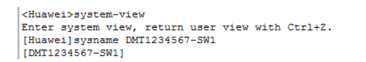
figure 2 计算机作业代写
- Configure the switches with VLANs and assign IP addresses to the interfaces based on the
results that you have obtained in Table 1.
➢ Take screenshots of the commands that you have entered to configure the switch SW1.
➢ Take screenshots of the commands that you have entered to configure the switch SW2.
➢ Take screenshots of the commands that you have entered to configure the switch SW3.
- Configure the PCs based on the results that you have obtained in Table 1.
➢ Take screenshots of your configuration on PCs.
Task 2: Dynamic Route Configuration 计算机作业代写
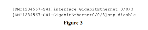
- Disable STP on the interfaces connected between the three Layer 3 switches. For example, you can enter the following command to disable STP on interface GE 0/0/3 of SW1 as shown in Figure 3.
- Configure RIP version 2 on each switch.
➢ Take screenshots of the commands that you have entered to configure the switch SW1.
➢ Take screenshots of the commands that you have entered to configure the switch SW2.
➢ Take screenshots of the commands that you have entered to configure the switch SW3.
- Verify the configuration by checking the routing table on each switch.
➢ Take a screenshot of the routing table on switch SW1.
➢ Take a screenshot of the routing table on switch SW2.
➢ Take a screenshot of the routing table on switch SW3.
-
Use the ping command to verify the connectivity between the PCs. 计算机作业代写
➢ Take screenshots of the ping results.
- Enter the tracert command to trace the route from PC3 to PC1.
➢ Take a screenshot of the traceroute result.
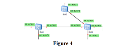
- Right-click the link between SW1 and SW2 and select “Remove Connection”. This will remove the link between SW1 and SW2 as shown in Figure 4.
- Enter the tracert command again to trace the route from PC3 to PC1.
➢ Take a screenshot of the traceroute result.
- Check the routing table on SW1 and SW2 to observe the changes of the RIP route information.
➢ Take a screenshot of the routing table on switch SW1 and SW2.
-
What are the changes? 计算机作业代写
➢ Discuss your observation in Step 7 and 8.10. List at least two problems that you have faced during the configuration in task 1 and 2. Discuss
how you troubleshoot and solve the problems. Support your answer with appropriate screenshots. If you have not faced any problems during the configuration, discuss how you achieve it.
- Enter the “save” command to save the current configuration of switch SW1, SW2, and SW3
respectively.
- Save your work in eNSP by clicking on the “Save As” icon on the top left of eNSP’s menu bar.
更多其他:C++代写 exam考试代考 article代写 MBA ESSAY代写 加拿大paper代写 c语言代写