ELEC3342: Digital System Designs
数字系统设计代写 There are 2 major parts in this homework. Part A includes questions that aim to help you with under- standing the lecture materials.
Homework 1
Due:
- Part (A) — 10 Oct, 2022,11:59pm
Instruction: Submit your answers electronically through Moodle.
There are 2 major parts in this homework. Part A includes questions that aim to help you with under- standing the lecture materials. They resemble the kind of questions you will encounter in quizzes and the final exam. Some of these questions may also ask you to implement and test small designs in VHDL. This part of homework must be completed individually.
Part B of this homework contains a mini-project that you should work in groups of 2. Your submitted work will be graded by an auto tester and therefore you should make sure your submitted files conform to the required format.
The following summarize the 2 parts.
| Part | Type | Indv/Grp |
| A | Basic problem set | Individual |
| B | Mini-project | Group of 2 |
In all cases, you are encouraged to discuss the homework problems offline or online using Piazza. However,you should not ask for or give out solution directly as that defeat the idea of having homework exercise. Giving out answers or copying answers directly will likely constitute an act of plagiarism, which is a serious offense.
Part A: Problem Set 数字系统设计代写
A.1
A.1.1 For each of the truth table in Figure A.1, do thefollowing:
(i)Draw the correspondingK-map
(ii)Minimizeusing K-map and write the resulting Boolean equation in canonical sum-of-products form;
(iii)Design a simple circuit corresponding to the truth table. You may use any gate with any number of inputs.
A.2
In class, we described a two-input XOR gate as gate that outputs TRUE if exactly 1 of its input is TRUE. Unfortunately, this description does not generalize directly to a 3 or more input XOR gate. In particular, consider the following functions with N variables x0, x1, . . . , xN−1: 数字系统设计代写
Y = x0 ⊕ x1 ⊕ . . . ⊕ xN−1
A.2.1Draw the truth table of the above function for the cases (a) N = 3 and (b) N = 4. Extrapolatingfrom the two truth tables, describe in words when the output is
A.2.2Leta, b, c, d be Boolean variables, proof the following by either using Boolean algebra or by using a truth table:
(i)a(b⊕ c) = ab ⊕ ac
(ii)(a⊕ b) ⊕ c = a ⊙ (b ⊙ c)
A.2.3Denote the exclusive XNOR operation as ⊙ , i.e., a ⊕ b = a ⊙ b. Proofthat:
a ⊕ b ⊕ c = a ⊙ b ⊙ c
A.3
You are designing a circuit with a 5-bit input n[4:0] and a single output d. d is 1 iff the input unsigned number represented by n is divisible by 6. HINT: 0 is divisible by any integer. Also, a number n is divisible by 12 iff it is divisible by both 3 and 4.
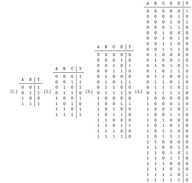
Figure A.1: Truth Tables for questions Question
A.3.1You start with designing a circuit that takes a 5-bit unsigned number n[4:0] as input and output 1 if the input is a multiple of 3. Design your circuit with VHDL called chkdiv3 with the following I/O ports:
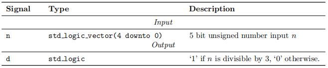
Submit your VHDL design called chkdiv3.vhd and a screenshot of its elaborated design.
A.3.2Now, using the fact that that all multiple of 4 end with the two bits ‘00’, and by reusing the chkdiv3 block from Part (a), design a circuit to check if the input number n is divisible by Name this circuitchkdiv12.
(i)Design the circuit of chkdiv12 by drawing its circuitschematic
(ii)Implement the circuit in VHDL, using chkdiv3 as a component.
Submit your VHDL design called chkdiv12.vhd, your original design schematic, and a screenshot of the elaborated design from your VHDL design. 数字系统设计代写
A.3.3Younotice that you can design a circuit that performs the same function as chkdiv12 by building the circuit directly from its truth table. Construct such circuit by
(i)Complete the truth table ofchkdiv 12
(ii)From the truth table, construct a circuit. Submit the schematic of this circuit.
A.3.3Comparing the two versions of circuits you designed above, which one is physically larger? You shouldestimate the size of a circuit by using the number of 2-input gates as a You can assume inversions (NOT) are free. Decompose gates with wider input into multiple 2-input gates.

A.4
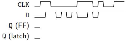
Given the input waveform below, sketch the output (Q), of :
(a)aD-latch
(b)aD-flip-flop
A.5 数字系统设计代写
An edge-triggered JK flip-flop functions similarly to an SR latch. A JK flip-flop has 2 inputs, J, K, and a clock signal clk. On the rising edge of the clock, it updates its output Q according to the following rules:
- If en is 0 on a rising edge of clk, the JK flip flop is disabled, otherwise, it behaves asfollows:
- If J and K are both 0, Q remains its oldvalue;
- IfJ is 1 and K is 0, then Q becomes 1;
- IfK is 1 and J is 0, then Q becomes 0;
- Ifboth K and J are 1, then Q toggles (1 becomes 0, 0 becomes 1).
Perform the following tasks:
(a)Designa JK flip flop with enabled using one D flip-flop and some additional combinational Submit the schematic of this circuit. 数字系统设计代写
(b)Implement your JK flip flop in VHDL. Submit your resulting file as Avhdl
A.6
Your lock has 2 buttons, labeled A and B. Starting in the state start, if it detects either one of the following sequences, then it will unlock by ending at the open state. The only way to retry is to reset the system back to the start state. Any other combination will lead to the state machine to the fail state. The only 2 correct sequences to unlock:
A → B → A → B
OR
A → A → B → A → B
If an incorrect button is pressed, the lock jumps to and stays at the fail state. The lock can be reset to the start start by pressing BOTH buttons (A and B) together at any time.
Your lock has one output called locked. It is asserted ‘1’ to close the lock, and is asserted ‘0’ when the lock is opened.
Perform the following tasks:
(i)Designa finite state machine (FSM) to implement this locking system by showing it state transition diagram.
(ii)Show the next state logic of the FSM as a truthtable
(iii)Show the output logic of the FSM as a truthtable
Part B: Project 数字系统设计代写
B.1 Music Code Decoder
This semester you will be building a complete hardware receiver for an innovative communication protocol called the Music Code, which was designed specifically for this course. In this homework, you will begin this journey by implementing the core decoding finite state machine (FSM). Your group will continue to improve the design in subsequent homework until you have a complete working system by the end of the semester.
Music Code Introduction Music Code is a simple communication protocol designed from the ground up that allows you (robots) to communicate through music. Specifically, messages are encoded as a sequence of musical notes in Music Code for transmission over the air. The decoder’s job is to listen to these encoded sequences of musical notes and to decode the original message.
Specifically, in Music Code, the following musical notes are used for communication. See the appendix for further information about the meaning of the musical note notation and frequency.
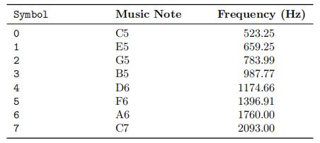
In other words, only eight (8) musical notes are used in Music Code. Each of the eight notes is uniquely identified by its numerical symbol index. For example, symbol 4 is the musical note D6, which has a frequency of 1174.66 Hz. 数字系统设计代写
In Music Code, messages are transmitted as streamlets. A streamlet always begins with a special beginning-of-stream (BOS) sequence and always ends with an end-of-stream (EOS) sequence. Encoded messages are transmitted within the two marks as a continuous data stream:
The messages within a streamlet are encoded using the following code table:
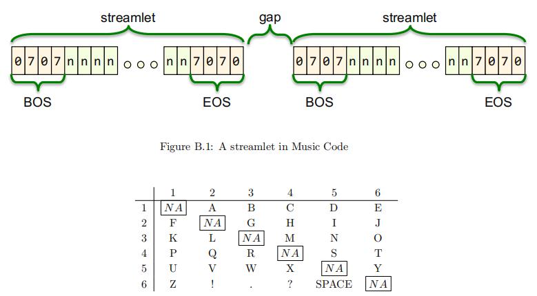
Figure B.1: A streamlet in Music Code
For example, the word “music” is encoded as the data sequence “3451452514”. Including the BOS and EOS marks, the following will be transmitted:
Message: “music” −→ Streamlet: 070734514525147070
B.1.1 Task 1: Music Code Decoder
Your main task for this homework is to develop the core music code decoder of the system, called mucodec. The task of mucodecis:
- Starting from reset, constantly monitor for the BOS mark.
- Onceit detects a BOS mark, constantly decode the data stream and output the decoded character.
- Endsthe decoding once the EOS mark is detected and return to wait for the next BOS.
- If at any point an error is detected during the data stream e.g. it detects a sequence not in the code book, it asserts the signal error for 1 cycle and ignores the rest of the streamlet. Decoding will resume once a BOS mark is detected again.
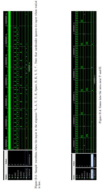
Figure shows a block diagram of your decoder.
Your decoder has the following input and output port:
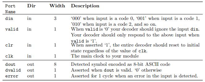
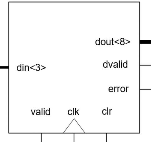
Figure B.2: Block diagram of Music Code decoder mucodec
B.1.2Example Run The waveform shown in Figure B.3 illustrates the expected behavior of your block whenthe input is the sequence “LATTE BEST!” (L, A, T, T, E, SPACE, B, E, S, T, !).
From the waveform, you will notice that your decoder reads in an input whenever valid is ‘1’. Once a valid character is detected, it output the corresponding ASCII value at din and assert dvalid for 1 cycle.
B.1.3 Submission
For this part of homework, submit as a group throughMoodle:
-
- the file mucodec.vhd that contains your completeddecoder
- A short report that describe your decoder.
In your report, you should explain the design of the decoder, including, but not limited to, how you detect the BOS and EOS mark, how you handle error, etc. Also, explain clearly how each person in the group has contributed to the design and implementation of the decoder.
A template for mucodec.vhd is available on the course website, together with a sample testbench.
B.1.4Appendix 数字系统设计代写
For those of you are interested in the science of music, the notation with a letter + number combination is called the scientific pitch notation (SPN). It is a method of specifying musical pitch by combining a musical note name and a number identifying the pitch’s octave, which is the interval between one musical pitch and another with double its frequency. For example, C3 is middle C, and C6 is the D note 2 octaves above middle C. In general, the frequency of a note determines its pitch. A note with higher pitch is produced by a wave with higher frequency. In particular, a note that is exactly one octave higher has doubled the frequency.
In terms of the produced sound wave, the volume of a note is determined by the amplitude of the wave. A loud note is produced by a wave with higher amplitude while a soft note has lower amplitude. 数字系统设计代写
Finally, the shape of the sound wave determines the timbre of the note. For example, the waveforms from a violin and a piano of the same note A4 will both have a central frequency of 440 Hz, but the shape of the two waves will look very differently.
Technically, the term “music” can be defined an organized collection of sound. In other words, music is created as soon as different notes are combined and organized at different rhythm. Using this definition, Music Code is indeed a form of music. In fact, music is one of the best forms of universal language to communicate, and Music Code is literally using this definition as a digital communication protocol.
更多代写:Python代上网课 托福代考多少钱 PSY心理学网课作业代写 PA代写 paper抄袭 代考Corporate Social Responsibility
合作平台:essay代写 论文代写 写手招聘 英国留学生代写