EE 210 Laboratory 07 Spring Semester
EE 作业辅导 Set the option for “Update Rate” to 100,000. This refers to the number of samples per second used to create the test file.
The purpose of this lab is to examine how the frequency-dependent properties of the capacitor can be used to make a tone-control circuit. Tone-control circuits are common in audio equipment – they allow the user to control the balance between treble (high frequency) and bass (low frequency) parts of a piece of music.
Pre-Lab Activities EE 作业辅导
- Read the laboratory supplement titled “Frequency Response”.
- Read the remainder of this handout.
- In Multisim, build the circuit shown in Figure 1 with C= 0.1 µF and R = 5.1 kΩ. This circuit looks like a simple voltage divider except that one of the resistors is replaced by a capacitor.
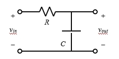
Figure 1. RC network.
1.Set up vinto be a 1 Vpp sinusoid with 0 VDC Offset, using a function generator.
2.Connect the oscilloscope in Multisim to monitor both vinand vout.
3.Measure the magnitude of vinand vout for frequencies of 20 Hz, 50 Hz, 100 Hz, 200Hz, 300 Hz, 400 Hz, 500 Hz, 600 Hz, 800 Hz, 1 kHz, 2 kHz, 3 kHz, 5 kHz, 10 kHz, 20 kHz.
4.Plot the magnitude of vout(in Vpp) vs. frequency (Hz) for all of the frequencies above. You should observe that the magnitude of the output signal changes as the frequency changes. This is very different than what would happen in a purely resistive circuit. EE 作业辅导
5.This type of circuit is called a filter– it filters out (removes/attenuates) certain frequencies while allowing other frequencies to pass through (remain). A low-pass filter is a filter that attenuates signals with frequencies higher than certain cutoff frequency and passes low-frequency In the range of audio frequencies we can think of such a filter as a “treble cut” filter.
A high-pass filter on the other hand passed the frequencies higher than cut off frequency and attenuates low frequencies and thus acts as a “bass cut” filter. Based on you results above, which kind of filter is this particular filter?
6.Upload your work to Canvas before the beginning of the lab.

In-Lab Activities
Required Items:
- myDAQ
- Parts Kit
- Breadboard and wires
Experiment 1: Observing the VI Characteristics of a Capacitor EE 作业辅导
In this first experiment you will measure the VI characteristic for a 0.1 µF ceramic capacitor and witness its frequency dependence.
Procedure:
- Build the circuit in Figure 2, with a slight modification. Connect a 68 Ω resistor in series with the function generator output to simulate a standard, practical source. The myDAQ function generator should be set to a 2 Vpp sinusoid with a frequency of 100 Hz.
Note: Normal function generators have a nominal source resistance of about 50 Ω, however the myDAQ analog outputs have a much smaller source resistance. Due to limitations in the myDAQ hardware, the simulated source resistance of 68 Ω must be added for this lab to work correctly.
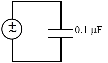
Figure 2. Test circuit for Experiment 1.
2.Set the myDAQ DMM as an ammeter to measure AC current through the 0.1 µF capacitor. Remember that the ammeter needs to be connected in series with the circuit element that it is measuring. For each stated signal frequency in the table on the lab worksheet, measure RMS current through the capacitor (from the DMM) and enter the measurements into the table.
Note: The DMM measures AC current in RMS (root-mean-square) value. This topic will be covered later in lecture. For now, you simply need to know that RMS value = 0.707 x amplitude = 0.3535 x peak-to-peak amplitude.
3.Now disconnect the DMM and set the myDAQ oscilloscope to measure the peak-to-peak voltage across the capacitor. For each stated frequency, measure the voltage and enter the measurements into your table. EE 作业辅导
To compare voltage and current measurements, you need to make sure that both are in the same form (e.g. amplitude, peak-to-peak amplitude, or RMS value). Since the DMM measures current in RMS units, the peak-to-peak voltage measurements will need to be converted to RMS units in the table (see note in #2 above).
4.It was stated earlier that a capacitor can be modeled as a frequency dependent “resistance” (more correctly – impedance). Use the equations below to determine the measured and expected impedance values for this 1 µF capacitor at each frequency and put your results in the table. The unit for impedance is the ohm.
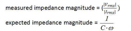
Note: ω=2π⋅f, where is the frequency in Hz.
5.Save a screen capture image of the oscilloscope display where the frequency is set to 10 kHz and upload it into the lab worksheet.
Q1 (answer on the lab worksheet): Comparing your measured impedance values with the expected values, what can you say about the assumed 0.1 µF capacitor value?
Q2 (answer on the lab worksheet): In your measurements, you should notice that the voltage across the capacitor starts decreasing significantly when the frequency gets very large. Based on your knowledge of voltage division, impedance, and source resistances, explain why you think this is happening. Hint: prelab question #3 may help as well.
Experiment 2: Measuring the Frequency Response of a simple RC circuit EE 作业辅导
In this next experiment, you will build an RC circuit and then measure its frequency response.
Procedure:
- Build the circuit in Figure 3 on your breadboard.
- Set themyDAQ oscilloscope to monitor the input voltage Vin on Channel 0 and the output voltage Vout on Channel 1.
- Set the myDAQ function generator to output a 1 Vppsinusoid with a frequency of 20 Hz. Connect the function generator to the input of your circuit.
- Measure the peak-to-peak voltage of the input and the output of your circuit. Compute the gain |Vout|/|Vin| of your circuit. Enter all values into the table on the worksheet.
- Repeat step 4 for each of the frequencies in the table.
- Compare your results with prelab question #3.
- Save a screen capture image of the oscilloscope display where the frequency is set to 100 Hz and upload it into the lab worksheet. EE 作业辅导
Q3 (answer on the lab worksheet): Compare your measurements with the values calculated in the Multisim prelab. How close are they?
Q4 (answer on the lab worksheet): Analyzing the data you have collected, what kind of filter is this circuit (lowpass, highpass, etc.)?
Q5 (answer on the lab worksheet): If you were to exchange the position of the resistor and capacitor, how would you expect the answer to Q4 to change? Why?
Q6 (answer on the lab worksheet): Even though we’re not changing the amplitude of the input signal when we take our various gain measurements, why is it vitally important to always measure the input in addition to the output of your circuits on your oscilloscope when calculating gain? What could happen if you only measured the output?
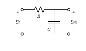
Figure 3. RC circuit: C = 0.1 µF, R = 5.1 kΩ.
Experiment 3: Baxandall Tone-control Circuit EE 作业辅导
In the EE 210 final project, you will design a circuit that performs a number of tasks. One of the tasks will be tone control – controlling the amount of treble and bass in an audio signal. You will be using a Baxandall tone-control circuit to accomplish this task. The theory behind the Baxandall circuit was covered in lecture. In this lab experiment, we will build this circuit and investigate its operation.
Procedure:
- Build the Baxandall tone-control circuit in Figure 4. The potentiometers Rp1and Rp2 are both 100 kΩ pots. Before inserting the pots, use the ohmmeter on the myDAQ to make sure that both pots are set in the middle, with equal resistance on each side.
- Connect the myDAQ function generator to your circuit and set itto output a 1 Vpp sinusoid with a frequency of 20 Hz. Set the oscilloscope to monitor the input voltage Vin on Channel 0 and the output voltage Vout on Channel 1.
- Sweep the frequency of the input through the entire audio frequency range (20 Hz – 20 kHz) and observe the effect of the input signal’s frequency on the output signal’s amplitude. EE 作业辅导
- Measure the peak-to-peak voltage of the input and the output of your circuit and compute the gain |Vout|/|Vin| for an input frequency of 20 Hz, 800 Hz, and 20,000 Hz. Record these measurements in the table on your lab worksheet.
Q7 (answer on the lab worksheet): What do you observe about the gain as a function of frequency?
- Rotate pot Rp1 all the way clockwise and repeat steps 3-4. In addition, try to find the approximate frequency at which the circuit starts or stops having an effect on the gain. It may or may not be a frequency that is listed on the table.
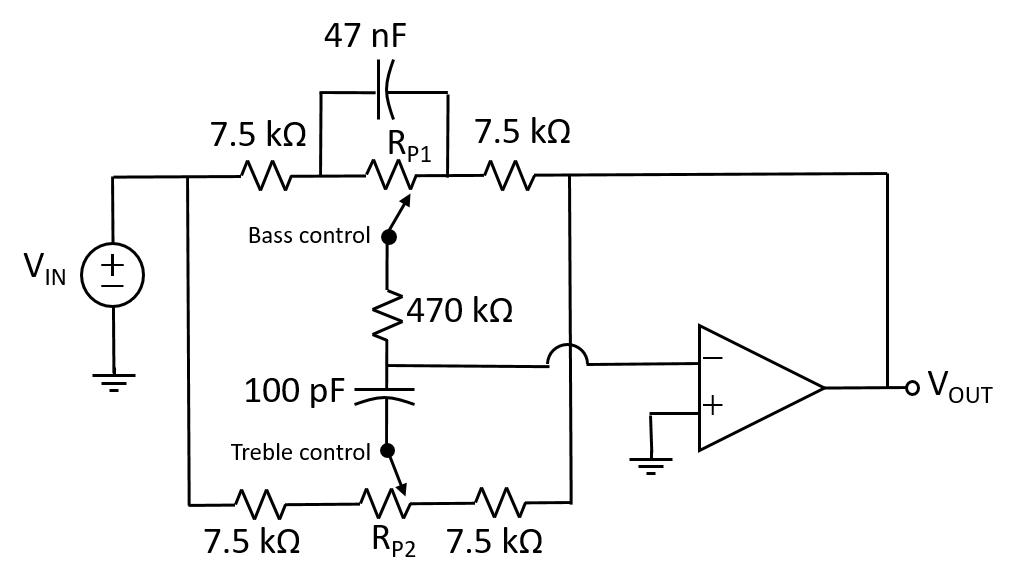
Figure 4. Baxandall tone-control circuit.
Q8 (answer on the lab worksheet): What do you observe about the gain as a function of frequency now? At which frequency does the circuit start or stop having an effect on the gain?
- Rotate pot Rp1all the way counterclockwise and repeat steps 3-4. In addition, try to find the approximate frequency at which the circuit starts or stops having an effect on the gain. It may or may not be a frequency that is listed on the table.
Q9: What do you observe about the gain as a function of frequency now? At which frequency does the circuit start or stop having an effect on the gain?
- Reset Rp1 to its center position and repeat the same steps above by varying Rp2instead of Rp1. Take gain measurements with Rp2 rotated all the way clockwise and again with Rp2 rotated all the way counterclockwise.
Q10 and Q11 (answer on the lab worksheet): Answer questions 8 and 9 again – this time discussing the effects of moving Rp2 to its two extrema instead of Rp1. EE 作业辅导
Q12 (answer on the lab worksheet): Based on your measurements, how do the minimum and maximum gains at frequencies of 20 Hz and 20 kHz agree or disagree with the expected performance of the Baxandall tone-control circuit based on the theory? Include calculations of expected minimum/maximum gain.
Q13 (answer on the lab worksheet): If the four identical resistors in the Baxandall tone-control circuit (Figure 4) were replaced by smaller resistors, what would you expect to happen to the maximum and minimum gains?
8.Now we’ll test the Baxandall circuit with an input test audio signal that consists of multiple frequencies. We will use the Arbitrary Waveform Generator tool to generate this signal.
a.Download the test file “1VSine440_3250.wdt” from Canvas and save it somewhere convenient.
b.Launch the Arbitrary Waveform Generator tool from the NI ELVISmx instrument launcher.
c.Next to the AO 0 Output Channel, click the folder icon, browse to the location you saved the test file, and click “OK.”
d.Make sure the box labeled “Enabled” is checked, and make sure the option for “Gain” is set to 1.
e.Set the option for “Update Rate” to 100,000. This refers to the number of samples per second used to create the test file. EE 作业辅导
f.Click “Run” to turn on the output.
9.Make sure AO 0 is connected to the input to the circuit, oscilloscope Channel 0 is measuring the input to the circuit, and oscilloscope Channel 1 is measuring the output of the circuit. Display voltage amplitude measurements for both channels.
10.While playing the test signal, slowly turn both potentiometers to various positions (both together and separately) and observe the effect that each one has on the signal.
11.Save a screen capture image of the oscilloscope display where both the treble and bass potentiometers are set to maximum and upload it into the lab worksheet.
Q14 (answer on the lab worksheet): Based on your measurements and observations, give a summary of what the Baxandall tone-control circuit does. Make sure to specifically address the roles of Rp1 and Rp2.
更多代写:cs代写机构推荐 gmat代考 英国assignment代写 医学essay代写 学生论文代写 代写留学生本科毕业论文