Course Project / Final
ECSE 2110
电力能源系统代写 This project aims to determine your ability to apply the concepts and methods discussed in class for an electrical energy system design problem.
Introduction…………………………………………………………………………………………………………………………………………3
Objective………………………………………………………………………………………………………………………………………………3
Design Project Statement and Data…………………………………………………………………………………………………………3
Design Problem Statement…………………………………………………………………………………………………………………….3
Transmission System…………………………………………………………………………………………………………………………….3
Substations Buses and Loads………………………………………………………………………………………………………………….5
Transformers………………………………………………………………………………………………………………………………………..5
Transmission Lines………………………………………………………………………………………………………………………………..6
Parameters for Existing Lines………………………………………………………………………………………………………………….6
Conductor Data………………………………………………………………………………………………………………………………………7
Transmission Towers………………………………………………………………………………………………………………………………7
Cost Data………………………………………………………………………………………………………………………………………………..7
Line Costs……………………………………………………………………………………………………………………………………………….7
Substation Costs………………………………………………………………………………………………………………………………………8
Design Phases………………………………………………………………………………………………………………………………………….9
Overview…………………………………………………………………………………………………………………………………………………9
Phase 1……………………………………………………………………………………………………………………………………………………9
Design Tasks……………………………………………………………………………………………………………………………………………9
Design Criteria and Specifications…………………………………………………………………………………………………………….10
Phase 2……………………………………………………………………………………………………………………………………………………11
Design Tasks……………………………………………………………………………………………………………………………………………11
Phase 3……………………………………………………………………………………………………………………………………………………11
Design Tasks…………………………………………………………………………………………………………………………………………….11
Phase 4…………………………………………………………………………………………………………………………………………………….12
Design Tasks…………………………………………………………………………………………………………………………………………….12
Phase 5……………………………………………………………………………………………………………………………………………………..12
Design Tasks……………………………………………………………………………………………………………………………………………..12
Design Criteria and Specifications………………………………………………………………………………………………………………..13
Criteria……………………………………………………………………………………………………………………………………………………….13
Specifications………………………………………………………………………………………………………………………………………………13
Phase 6 (Optional – Bonus Points!)………………………………………………………………………………………………………………..14
Design Tasks……………………………………………………………………………………………………………………………………………….14
Design Criteria and Specifications…………………………………………………………………………………………………………………14
Report Requirements and Structure………………………………………………………………………………………………………………16
Final Remarks……………………………………………………………………………………………………………………………………………..19
Plan your work and start early!……………………………………………………………………………………………………………………..19
Preparing Your Submission:………………………………………………………………………………………………………………………….19
Do your own work!……………………………………………………………………………………………………………………………………….20
Appendix – Conductor Data for Transmission Lines…………………………………………………………………………………………21
Introduction 电力能源系统代写
This project aims to determine your ability to apply the concepts and methods discussed in class for an electrical energy system design problem. You can develop your own software in your language of choice, and/or use the software tools utilized in the class (i.e. MATLAB, EMTP-RV and/or Flux).
Objective
- To carry out the design of a power transmission system that runs through both urban and rural service territories.
- To apply your knowledge from class in computing parameters for component models and perform system wide-analysis under steady-state conditions.
- To build software scripts and use different software tools towards your design.
- To document your results and source code in a report.
Design Project Statement and Data
Design Problem Statement
The design problem consists in expanding a transmission system to serve a new data center called “Steel Mill” (indicated with a red square and red numbers in the map in Fig. 1) and to also determine if the existing transmission system needs to be upgraded to handle a 30% growth in the existing load. This requires to design and build new transmission infrastructure, and to perform power flow, contingency analysis, and fault analysis studies. 电力能源系统代写
Important:
- The location of the “Steel Mill” has not been yet decided. Each student will do their own design according to the following list: here
- Use the following link to download a figure with better resolution to take measurements from: here.
Transmission System 电力能源系统代写
The transmission system in Figure 1, below, contains both 161 kV and 69 kV transmission lines and substations that go through both urban and rural service territories. Assume that all roads go from North to South and East to West. The load at each of the buses is provided in Table 1, and the parameters of the existing lines are shown in Table 2.
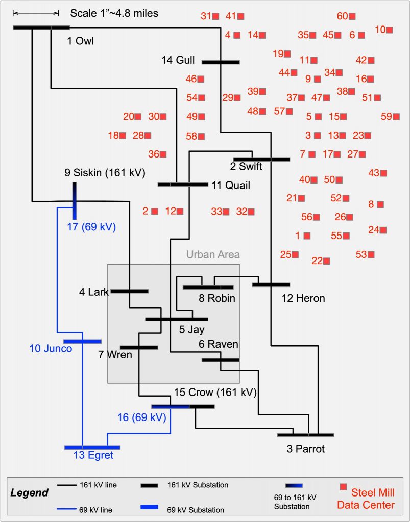
Figure 1. Eagle Power System Transmission Map
Substations Buses and Loads
The buses shown in the diagram correspond not only to electrical buses, but to substations that may contain transformers and other components as discussed next:
- Buses 1-3 are substations at power sources (i.e. generation plants) at 161 kV.
- Each power source is rated at 490 MW, with a minimum volt ampere reactive limit of -100 MVAr and a maximum limit of 250 MVAr.
- Buses 4-8 are urban load substations
- Buses 9-15 are rural load substations
Buses with loads under 30 MVA should be served at 69 kV and buses with loads over 50 MVA should be served at 161 kV. Other buses can be served at either voltage, as discussed later. 电力能源系统代写
| Bus # | Bus Name | Load (MW) | Load (MVAr) |
| 1 | Owl | ||
| 2 | Swift | ||
| 3 | Parrot | ||
| 4 | Lark | 60 | 10 |
| 5 | Jay | 100 | 30 |
| 6 | Raven | 80 | 15 |
| 7 | Wren | 90 | 20 |
| 8 | Robin | 40 | 5 |
| 9 | Siskin | 10 | 5 |
| 10 | Junco | 15 | 10 |
| 11 | Quail | 75 | 15 |
| 12 | Heron | 40 | 15 |
| 13 | Egret | 30 | 10 |
| 14 | Gull | 35 | 10 |
| 15 | Crow | 10 | 0 |
| Total: | 585 | 145 |
Table 1. Loads at different buses
Transformers
There are 69 kV to 161 kV transformers with 60 MVA rating at the Siskin and Crow buses. Each of the buses have 2 voltage levels. At Siskin, the high voltage side is labeled bus 9, while the low voltage side is labeled bus 17. At Crow, the high voltage side is labeled bus 15, while the low voltage side is labeled bus 16. The transformers have leakage reactances of 34.56Ω referred to the 161 kV side.
Transmission Lines
Parameters for Existing Lines
The parameters of the existing transmission lines are provided in Table 2, below.
| Bus # | Bus # | Bus Name | Bus Name | Miles | Conductor | R (Ohmns) | X (Ohmns) | BMVA |
| 1 | 9 | Owl 161 | Siskin 161 | 24 | Drake | 3.085 | 17.47 | 3.629 |
| 1 | 11 | Owl 161 | Quail 161 | 36.7 | Drake | 4.718 | 26.7 | 5.55 |
| 1 | 14 | Owl 161 | Gull 161 | 28.2 | Drake | 3.629 | 20.53 | 4.264 |
| 2 | 11 | Swift 161 | Quail 161 | 21.5 | Drake | 2.774 | 15.66 | 3.251 |
| 2 | 12 | Swift 161 | Heron 161 | 20.3 | Drake | 2.618 | 14.78 | 3.07 |
| 2 | 14 | Swift 161 | Gull 161 | 24 | Drake | 3.085 | 17.47 | 3.629 |
| 3 | 6 | Parrot 161 | Raven 161 | 27.6 | Drake | 3.551 | 20.09 | 4.174 |
| 3 | 12 | Parrot 161 | Heron 161 | 27.6 | Drake | 3.551 | 20.09 | 4.174 |
| 3 | 15 | Parrot 161 | Crow 161 | 23.6 | Drake | 3.033 | 17.16 | 3.569 |
| 4 | 5 | Lark 161 | Jay 161 | 8.4 | Dove | 1.529 | 6.3 | 1.232 |
| 4 | 9 | Lark 161 | Siskin 161 | 18.8 | Drake | 2.411 | 13.69 | 2.843 |
| 5 | 6 | Jay 161 | Raven 161 | 10.8 | Dove | 1.97 | 8.09 | 1.584 |
| 5 | 7 | Jay 161 | Wren 161 | 6 | Dove | 1.089 | 4.48 | 0.88 |
| 5 | 8 | Jay 161 | Robin 161 | 10.9 | Dove | 1.996 | 8.17 | 1.599 |
| 7 | 15 | Wren 161 | Crow 161 | 14.6 | Drake | 1.866 | 10.63 | 2.208 |
| 8 | 12 | Robin 161 | Heron 161 | 9.8 | Drake | 1.27 | 7.13 | 1.482 |
| 5 | 11 | Jay 161 | Quail 161 | 19.5 | Drake | 2.514 | 14.18 | 2.949 |
| 10 | 13 | Junco 69 | Egret 69 | 14.3 | Hawk | 3.033 | 10.15 | 0.408 |
| 10 | 17 | Junco 69 | Siskin 69 | 16.2 | Hawk | 3.433 | 11.49 | 0.462 |
| 13 | 16 | Egret 69 | Crow 69 | 21.9 | Hawk | 4.642 | 15.54 | 0.624 |
| BMVA: reactive volt-amperes generated by the total susceptance corresponding to line charging of the transmission line at rated voltage. | ||||||||
Table 2. Transmission Line Parameters
The BMVA is determined as follows. The susceptance of the line as ![]() , consequently the BMVA can be calculated from:
, consequently the BMVA can be calculated from:
![]()
Conductor Data
- Conductor Types: For new lines that have to be built the only conductors available to use are Partridge, Hawk, Dove, Drake and Cardinal, and their data is available in the Appendix.
- Ampacity: the maximum current carrying capacity (or ampacity) of the allowable conductors types listed above are: Partridge (475 A), Hawk (659 A), Dove (726 A), Drake (907 A), Cardinal (996 A). 电力能源系统代写
Transmission Towers
The transmission line towers used in this service area at 161 kV and at 69 kV levels are shown in the Figure below. You can use more modern designs, provided that they are appropriate for 161 kV and 69 kV voltage levels.
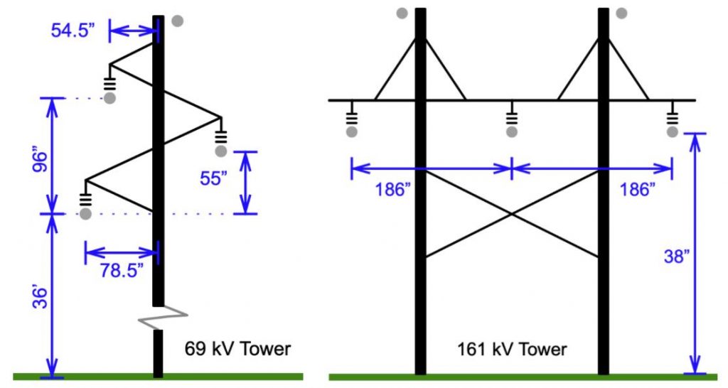
Figure 2. Transmission Tower Structures (69 kV and 161 kV)
Cost Data
Line Costs
The following costs include the conductors, right-of-way, structures, shield wire, etc, and is provided in $/mile.
| 161 kV | 69 kV | |||
| Conductor size | Urban | Rural | Urban | Rural |
| Partridge | $109,000.00 | $75,000.00 | ||
| Hawk | $113,000.00 | $83,000.00 | ||
| Dove | $243,000.00 | $106,000.00 | $115,000.00 | $85,000.00 |
| Drake | $257,000.00 | $115,000.00 | $126,000.00 | $92,000.00 |
| Cardinal | $264,000.00 | $120,000.00 | ||
Table 3. Line Costs
Substation Costs 电力能源系统代写
Assume that the basic substation sites exist at each bus 1-15. If you add a substation, then you must add to your costs the basic site cost for the new substation. Do not add the site costs for buses 1-15.
- The basic site cost is $300,000.00 and includes land, fence, grading, and structures.
- Each line breaker and line termination need to include a circuit breaker at each end of the line, for the given voltage ratings:
- 161 kV: $95,000.00 per three-phase breaker
- 69 kV: $48,000.00 per three-phase breaker
- Transformers and associated equipment including 161/69 kV circuit breakers have the following costs:
- 60 MVA: $900,000.00
- 120 MVA: $1,000,000.00
- 180 MVA: $1,100,000.00
- Capacitor Banks:
- Installation and associated equipment: $60,000.00 per bank.
- Capacitors: $300 / 100 kVAr
Design Phases
Overview
The project is structured so that you conduct this project in different phases, as follows:
- In the first phase of the design, the only requirement is to choose the conductors and conductor spacings for the two voltage levels, and determine the corresponding impedance parameters of the lines. To this end, it is possible to use the software provided with the textbook, EMTP-RV or make your own scripts. A cost analysis needs to be performed, and use the costs provided earlier in the statement. It is preferable to use realistic numbers by researching online, but not required. If you do so, please indicate it clearly so that this can be considered in your grading. 电力能源系统代写
- The following phase consists of transforming all the data to per unit quantities.
- The third phase of the design requires to consider the location of the power generators and to determine from data tables what the most adequate parameters to use are.
- The fourth phase consists in using the per-unit data of all system components to compute the Ybus matrix.
- The fifth phase consists in a power flow study of the system under different load growth scenarios
- The sixth phase involves contingency analysis to identify the impact of failures in certain components of the system.
Phase 1 电力能源系统代写
In this phase you are asked to upgrade the existing system making minimum cost design to serve the load and generation subject to the following specifications and design tasks.
Design Tasks
a.Provide sufficient capacity in the transmission lines and transformers for a 30% growth of the existing load.
b.The new “Steel Mill Data Center” will host a major IT operation for the new federal Department of National Cyber-Infrastructure. This will be a critical load. It is estimated that the load will be 40 MW at unity power factor. It is not yet decided where it will be located, the red squares and numbers as shown in the map in Fig.
1 indicate potential locations. Check the list hereto determine which location is assigned to you. Your task is to design a suitable transmission system configuration to supply the load, which would expand the existing network. However, keep in mind that you must find a trade-off between cost and reliability.
c.Transmission voltages of 161 kV or 69 kV can be used. Bundled conductors are not to be used at these voltages.
d.In the event of a single failure of a line, a transformer, or a power source, the system should continue to supply all the loads.
e.Calculate impedances of all the new transmission lines using suitable software. You can make your own, use something from the textbook or use EMTP-RV. The resistance of lines should be calculated at 50 deg. C. The line capacitance in terms of the megavolt-amperes-reactive (MVAr) generated by the total capacitance of susceptance at rated voltage is provided in Table 2. You need to calculate these quantities for any new transmission line added. 电力能源系统代写
f.Each power source (generator) should be connected to the rest of the system by at least three 161 kV lines. Even if one fails, the remaining two should be capable of carrying the dispatched power.
g.Seek a minimum cost design. Do not oversize conductors without justification.
h.The maximum number of available transformers that you can use for your design is six.
i.It is unlikely that you can justify using the same conductor size at both 161 kV and 69 kV.
j.Line routes should follow transmission line routing regulations (i.e. road right-of-way).
Design C riteri a and Specifications
In performing the above steps, you will need to verify that the transmission lines and transformers have sufficient current carrying capacity (ampacity) even under various failure conditions. This can be done accurately using power flow calculation programs, as done in the fifth phase. In this phase, however, you should instead start by making a rough estimate.
Because you are given the existing voltages and loads at each bus, you can compute an estimate of the load currents. For simplicity, assume that increasing the loads by 30% increases the currents proportionally. Once the current of a particular bus has been determined, the next step is to figure out how much of this current is supplied by each of the transmission lines to the bus. Of course, one could use the current divider approach, however, this would require additional data and computations that are not possible at this point.
To compute this estimate, you have two options. One option is to build the system model and perform a power flow. The second option is to take an intuitive approach using the “electrical distance” concept, described next.
The electrical distance is a measure of the equivalent impedance between two nodes. When 2 buses are electrically close, the equivalent impedance between them is low, and vice versa.While geographical closeness and electrical closeness are mostly related, this is not always the case, as it depends on the value of the impedances between two buses.
For example, intuitively, bus 11 is connected to generator bus 1 through a single line, whereas there are many other lines and equipment from bus 3 to generator bus 11. So, you can expect that at bus 11 there is more current coming from bus 1 than bus 3. 电力能源系统代写
Hence, a simplified approach to quantify electrical closeness is to consider a particular load bus and determine the impedance of all paths between the load bus and generator buses. First, you can calculate the impedance for all possible transmission paths between bus 11 and generator bus 1, which include paths (1-11), (1-14-2-11), (1-9-4-5-11), etc. Next, find the lowest impedance path. In practice, some paths (those with many segments) can be ignored.
If the result is a low impedance, bus 11 is “close” to generator bus 1. Similarly, it is possible to find the lowest impedance path from bus 11 to bus 2, and from bus 11 to bus 3.
For simplicity, it can be assumed that the currents to bus 11 only flow in the three lowest impedance paths and that they divide according to the parallel current rule. Thus, the lower the path impedance, the greater the fraction of the total current that flows in that path. This should provide results that would be reasonable, at least qualitatively.
This process should be repeated for all the other load buses. When doing this, it may happen that a particular transmission line, e.g. (1-11) is also a segment of a lowest impedance path, say, from generator bus 1 to bus 5. In this case you will add the two contributions (as scalars) to find the total current in (1-11).
Regardless of using either approach, you should automate the calculations by writing your own program in MATLAB or another language/tool of your preference, otherwise, you would spend too much time analyzing each load bus, you need to automate the estimation process!
Phase 2
This phase consists in transforming the data from the system designed in Phase 1 to per unit.
Design Tasks
For the system designed in Phase 1:
k.Calculate all the impedances on a 100 MVA base, with a voltage base of 161 kV or 69 kV as appropriate.
l.The transformer reactance is 0.08 pu on the transformer base. You can ignore the resistance or find the value in per unit by making your own assumptions.
Create a table with all the parameters of the system in per unit.
Phase 3 电力能源系统代写
This phase consists in determining parameters for the generators in the system.
Design Tasks
The power system in Fig. 1 has three power plants located at Bus 1 (Owl), Bus 2 (Swift) and Bus 3 (Parrot). Assume that these three generators have a rating of 550 MVA each, and recall that each of the generators is rated at 490 + j250 MVA.
m.Determine the parameters , and that characterize the synchronous generator model with saliency.
This task requires you to perform a literature survey. To determine the parameters required, you can consult different books that include parameter tables of power system equipment (Tip: look in books that involve power system dynamics, handbooks, etc.). You are expected to look up at least 2 references, and make appropriate assumptions on what type of power plant this involves (e.g. fossil-fired steam generator, hydro, etc), and select parameters that fit the ratings defined earlier.
n.Convert all machine parameters to a common system base of 100 MVA and the appropriate voltages.
Phase 4
This phase is a continuation of Phases 3 and 4 and consists of building the Ybus.
Design Tasks
For the parameters determined in Phases 3 and 4, perform the following calculations.
o.Learn to use the software from the book or develop your own code to compute Ybus. 电力能源系统代写
p.Compute the Ybus matrices with all the parameters expressed in per unit values on the common system base of 100 MVA.
q.Display and analyze the sparsity properties of the Ybus matrices in graphical form (eg. in Matlab you can use spyor cspy functions).
Phase 5
This phase consists in performing different power flow studies for the system set up in the previous phases. You will consider the following case studies:
- Case 1:Base case system with base loads and fixed tap transformers
- Case 2:Base case system with base loads and tap-changing transformers.
- Case 3: Modified system with 40 MW “Steel Mill Data Center” load and base case loads increased by 30% and tap-changing transformers.
Design Tasks
r.Use the software of your choice to perform power flow analysis on Case 1 and verify the design requirements listed below.
s.Use the software of your choice to perform power flow analysis on Case 2 and verify the design requirements listed below.
t.Modify the transmission system to supply the new 40 MW load following the specifications a-j in Phase 1.
- Obtain the parameters of the lines as needed by the power flow program of your choice, and provide a new table of data highlighting the new parameters used.
- Use the software of your choice to perform power flow analysis on Case 3 and verify the design requirements listed below. 电力能源系统代写
u.Summarize graphically (one plot for the same variable for the three Cases) the power flow results from the three cases analyzed above, show the bus voltage magnitude and angle, active and reactive powers.
v.Determine the total power (P) loss in the system as a percentage of the total load for each case. Compare the MVA in the loads, the MVA used in the lines and the transformers, the MVA from line charging, and the MVA from the generators in each case.
See: https://www.mathworks.com/matlabcentral/fileexchange/46551-cspy-m
Design Criteria and Specifications
Criteria
When carrying out the design tasks above, you must meet the following design criteria:
- Satisfactory system operation:all voltages should be in the range from 0.96 to 1.04 pu, with no overloaded lines or transformers.
- Loads:from the power flow results, determine the total load in the system, the losses and total generation. What is the generation at the slack bus?
- Transformers:the transformer tap should be fixed at 1.00 (Tap 1 is 69 kV and Tap 2 is 161 kV) in the power flow for Case 1 and changed to a tap-changing transformer for Case 2 and 3.
- Tap-Changing Transformers:set each transformer to regulate the voltage on the 69 kV bus. Select a scheduled voltage and include it in the bus data. Specify a tap range of (0.9 to 1.1 per unit) 62.1 kV to 75.9 kV. 电力能源系统代写
For Case 3, If any of the criteria above are violated you will need to modify your design and re-do the analysis until the modified system meets the criteria.
Specifications
The specifications below are to assist you in meeting the design criteria.
- Generation:
- Make Bus 1 (Owl) the slack/swing bus.
- For the generation at Bus 2 (Swift) and at Bus 3 (Parrot) change the following at both: Qmin – 100.00 MVA and Qmax 250.00 MVA, and Pmax at 430 MW.
- In Cases 1 and 2, Pgen at each bus (2 and 3) should be 190 MW. In Case 3, change the Pgen at each bus to more appropriate values. Since the voltage is usually highest at generator buses, and since 1.04 is at the upper limit of acceptable voltages, schedule the voltage on the three generators at or near 1.04 per unit.
- Naming Conventions and Plotting:for each power flow you run, you must summarize the results in graphical form (e.g. using bar plots) and in the title, you need to specify the case as C1 for Case 1, C2 for Case 2, etc.
- Check your data!:as you will have to modify either the one-line diagram or data files for the power flow program, you need to be careful when modifying it. Be consistent with naming conventions you will use as you make modifications to each case, use descriptive names, and add comments to the source file or diagram. Spend time checking that you are applying the correct changes to the files and that they are modifying the output as expected. Also check that all the lines are connected to the correct buses. These are typical issues when doing these kinds of studies.
Phase 6 (Optional – Bonus Points!) 电力能源系统代写
This phase consists of performing a contingency analysis to test the steady-state performance of the system when contingencies are applied. The goal is to use the power flow program to analyze the performance of the system and test its ability to perform within specific requirements after a disturbance.
Design Tasks
w.Develop your own program for N-1 contingency analysis. What this means is that the program should be able to provide results when considering the failure of each transmission line, transformer, and generator. Create a flow-chart of your routine and document the source code.
x.Perform an exhaustive contingency analysis, considering the failure of each transmission line, transformer, and generator, for Cases 1, 2 and 3 when each generator is scheduled at its maximum generation capacity of 430 MW.
Synthesize the results from the previous task graphically for easy interpretation. Try to minimize the number of plots by including results from each variation (case, outage, modification) within the same figure. Be creative!
Design Criteria and Specifications
The specifications below are to assist you in meeting the design criteria.
- Loads:the increased load (30%) and the new “Steel Mill Data Center” load will be used in all outage cases.
- Transformers:for all cases, set each transformer to control the voltage on the 69 kV bus.
- Generation:
- For cases where you remove lines or transformers, set the power at bus 2 and at bus 3 to 270 MW.
- For the generator outage cases, you should select the power schedules (e.g. the two remaining generators can be set to share supply the total load approximately equally). In addition, you must change the bus at which you lose a generator to a PQ bus with zero load (it is not sufficient to set the P generated to zero, as the bus will continue to regulate the voltage as it is set to a PV bus). 电力能源系统代写
- For the cases in which you schedule each generator at its maximum, lower the generation at the other two buses (e.g. the two share the remaining generation approximately equally).
-
Naming Conventions and Plotting:for each case, you must summarize the results in graphical form (e.g. using bar plots) and in the title, you need to specify the case as C1 for Case 1, C2 for Case 2, etc.
- Enforce Limits:you must enforce limits to check that voltages are in the allowable range (0.96 to 1.04) and that there are no line overloads. If your designed system still presents violations, change it so that it satisfies all of them. Keep in mind that a change that solves one problem in one case may create different problems in other cases.
- Capacitor Banks:if you choose to use a capacitor bank to solve low-voltage problems, remember that this needs to be accounted for in your cost estimation. Remember to note where you added the capacitor bank and the capacity and recalculate your costs.
- Systematic Analysis: before you make any changes to the system, you should analyze the impact of all the outages in the contingency analysis. Doing a systematic analysis will allow you to identify where the problems arise from and would facilitate making a smaller (and less costly) addition to fix the system.
Report Requirements and Structure 电力能源系统代写
Your report should be structured as described below.
1.Executive Summary: a maximum 1-3 page summary that includes the main information of your project.
This should contain everything that I need to know to grade you without having to read the whole report. Make this a “self contained” document.
Your summary should include at least the following:
a.Total number of lines at each voltage level, total line miles and cost at each voltage level. 电力能源系统代写
b.The total number of transformers and cost.
c.The total number of new substations and cost.
d.The total number of capacitor banks and cost.
e.Potential upgrades and their cost (e.g. upgrading circuit breakers).
f.Summarize the changes required at each phase using a table. Make a table that has as either rows or columns the relevant phases (i.e. Phase 1 and 5 (and 6 if you chose to do it for bonus points)).
g.Contrast the analysis methods and results of Phase 1 and 5 (and 6 if you chose to do it for bonus points).
h.Use a minimum of 1 figure and a maximum of 2 figures to highlight your most important finding.
2.Report Structure:
a.Title page (include the Academic Integrity statement as with other submissions).
b.Table of contents.
c.System Description
i.A transmission map of the system with modifications (i.e. clearly showing your final design, e.g. use different colors), including the line routes and voltages.
ii.A one-line diagram of the system showing the bus, line, transformer, and load connections. Don’t forget to include capacitor banks if they were needed in Phase 5 (or 6 if you chose to do it for bonus points). They should be included in your cost estimation!
iii.Specifications of a representative transmission structure for each voltage level, as used for conductor spacings and impedance calculation Phase 1. Include a drawing of each structure. Cite the source of the information about the structures. 电力能源系统代写
iv.Specifications of each line in the system: connection between buses, voltage, length, conductor size, cost estimate, series impedance and shunt capacitance susceptance, and MVA and current ratings. For the new lines added to supply the “Steel Mill Data Center”, show a sample impedance and susceptance calculation. Summarize all remaining results from Phase 1 in a dedicated Appendix.
d.Design Summary
i.Provide a summary of results from all other design phases here. You should aim to summarize each phase with a short paragraph and preferably through 1 or 2 figures. All other details (calculations, tables, figures) for each design phase should be included in a dedicated Appendix (one Appendix section for each design phase).
ii.Design Analysis:
-
-
- Summarize the changes required at each phase using a table. Make a table that has as either rows or columns the relevant phases (i.e. Phase 1 and 5 (and 6 if you chose to do it for bonus points)).
- Contrast the analysis methods and results of Phase 1 and 5 (and 6 if you chose to do it for bonus points).
- Use a minimum of 1 figure and a maximum of 2 figures to highlight your most important finding.
-
iii.Design Tools:
-
- Software Documentation: Briefly explain, through a flowchart and discussion, how you were able to do the analysis required through different software routines or by using different functions/software and reading data. Make a flow-chart of how your different functions/tools are called, the required input data, etc.
- Summarize what would be the most desired functionalities that you would like to have if you had to do this all over again.
e.Cost Estimation:
i.Specification of each new line in the system: location, cost.
ii.Specification of each transformer in the system: location, cost. 电力能源系统代写
iii.Specification of each added substation: location, cost.
iv.Specification of each capacitor bank in the system: location, cots.
v.Specification of any additional upgrades of existing equipment: location and cost.
vi.Summarize the cost estimates by contrasting the relevant design phases and how the cost changes based on the results from each analysis (i.e. Phase 1 and 5 (and 6 if you chose to do it for bonus points)).
f.Conclusions: briefly discuss your findings. Keep this short, 1-2 paragraphs, 1 figure, and highlight your most important finding.
3.Other:
a.Number and title all figures.
b.Number and title all tables.
c.Document all changes made from the base case design in a dedicated Appendix, be organized!
d.Document, for each phase, in a dedicated Appendix, the results from each task.
Final Remarks 电力能源系统代写
Plan your work and start early!
- This project covers all the course topics and requires you to proactively start working on it. If you wait until the end of the lectures to work on it, you will not be able to finish in time or do a good job.
- As I am giving ample time to ask questions about this project during office hours, I will not respond to any questions after the office hours after 12/10, which is the last day of class according to the schedule.
- Suggested timeline:For your planning I have prepared a table that you can use to keep track of your project’s work:
| Milestone | Suggested Date of Completion |
| Project description read and understood | 9/17 |
| Go to office hours to ask questions | 9/21 |
| Phases 1-3 Completed | 10/26 |
| Phase 4 completed | 11/16 |
| Phase 5 work started | 11/17 |
| Phase 5 work completed | 12/10 |
| Prepare the report | 12/11 |
| Prepare presentation | 12/12 |
| Record Video | 12/12 |
| Early submission | 12/12 |
Preparing Your Submission
- Your project submission will consist of:
- A report, documenting all of your results and analysis.
- A presentation (use Google Slides, PowerPoint, etc), to be used for a video recording. 电力能源系统代写
- A recorded video presentation summarizing your report, and highlighting your main findings.
- You must follow the same submission procedure as all the other assignments, meaning that you have to provide: ./report/, ./presentation/, ./sourcecode/ and ./other/
- Check the requirements on the course syllabus!!!
Do your own work!
- This project serves as a way to measure your ability to apply the intended learning outcomes. You must make sure during the course that you will be able to do the work described here, and thus, you should do all the homework assignments to be able to have the skills you need.
- This project has no unique solution, there is no possible way that you can have the same solution as another student, if I detect any similarities, I will give both of you a zero.
- This course does not allow any collaboration or joint work with others, see the course policies.
Appendix – Conductor Data for Transmission Lines
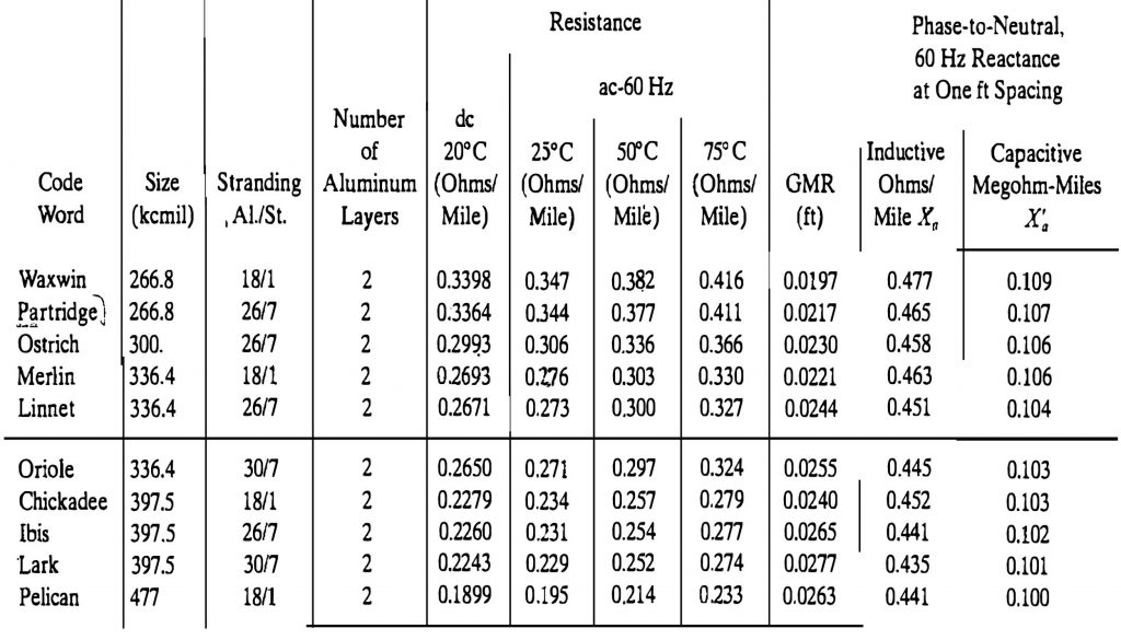
Figure 3. Bare Aluminum Conductors, Steel Reinforced (ACSR) Electrical Properties of Multilayer Sizes
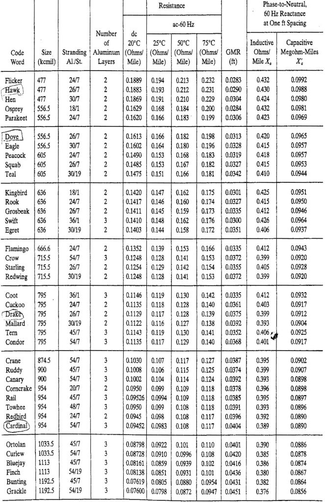
Figure 4. Bare Aluminum Conductors, Steel Reinforced (ACSR) Electrical Properties of Multilayer Sizes
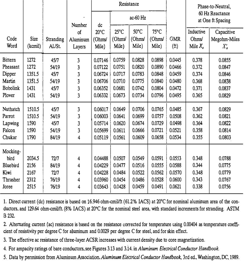
Figure 5. Bare Aluminum Conductors, Steel Reinforced (ACSR) Electrical Properties of Multilayer Sizes
更多代写:it代考 托福代考 英国留学生代考推荐 Essays论文代写 留学生论文作业代写 代写论文枪手价格